The Front Panel Connectors alternatively referred to as the Front Panel Header or FPanel, are a string of different connections on the motherboard that controls the computer’s case power on, reset, beep code speaker, USB ports, and LED indicators.
In short, it can be said that the front panel connectors on the motherboard control every aspect of the PC case.
However, to truly understand what the front connectors really are, we will have to dig a little deeper and see all the different aspects of these connectors.
In this article, I will cover everything about front panel connectors so you will no longer be confused at the end of your read.
You will get to know what they are, how they function and look like, how to locate them, and, lastly, how to connect front panel connectors to the motherboard.
There is a lot to cover. So, without further ado, let’s begin.
So, What Are Front Panel Connectors?
I have already given you a sneak peek about what front panel connectors are, so let’s dive into more detail and evaluate it further.
The primary task of the front panel connectors is to be the part of the motherboard that serves the connection needs of the PC case. Every PC case has a couple of buttons, some ports, and some led indicators built into it. This is also termed the front I/O of the PC.
Of course, the PC case cannot power these ports, buttons, and led indicators, so they need to be connected to the motherboard. To connect the PC case front I/O, we use the front panel connectors of the motherboard.
The front panel connectors are different from the other typical motherboard connectors. They are small, and each socket has a specific number of pins. The number of pins is different in each socket, depending on its functionality.
Generally speaking, there are 5 different types of front panel connectors that every motherboard has. They are:
- Power Switch Pins: Sometimes also called PWRSW or PW these pins connect the power button of the PC case to the motherboard.
- Reset Switch Pins: The reset pins are the two pins that connect the reset button of the PC case to the motherboard.
- Power Led Pins: The power led consists of 3 pins that connect the case status led to the motherboard. The status led on the PC case is used to tell if the PC is on, off, or in sleep mode.
- Hard Disk LED Pins: The hard disk led pins are 2 pins that connect the storage drive LED indicator to the motherboard. The HDD LED indicator tells the hard drive’s activity by flashing if the hard drive is in full swing and solid if the hard drive is being sparingly used.
- Speaker Pins: The 4 speaker pins connect the beep code speaker to the motherboard, which is used for listening to any errors. The beep codes it gives play a crucial role in testing a motherboard for faults. The beep code speaker is not the same as the stereo speaker. It only gives out audio in the form of beep codes for any errors present when booting up the PC and cannot be used to play any media or songs.
Besides these five, there are also some other forms of front panel connectors, but they are not used much these days. Therefore, I will go over them just briefly.
- Serial headers: Used for two standard serial port connections and one mini-serial power connection.
- IDE Connectors pins: These pins provide access to the internal hard drive, therefore, ensuring that no data is lost during power outages or surges
- Molex connector: These Molex connectors are used for CD/DVD ROMs.
- PS/2 headers: Used for old mice and keyboards with rounded cable types. Not used anymore.
What Do the Front Panel Connectors Look Like?
The front panel header is a single block on a motherboard containing many small pins. Think of this as the size of an ATX power connector because it has individual pins related to specific functions.
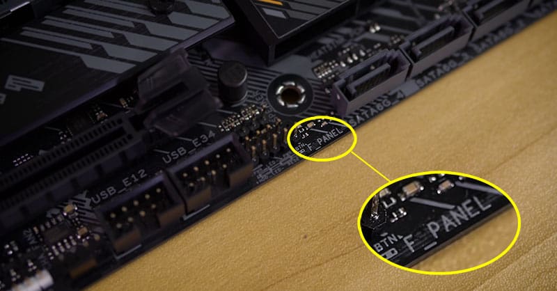
The picture down below will further clarify what a front panel connector looks like in a motherboard.
Depending on the motherboard, the front panel connectors can either have an enclosure or casing around them. In contrast, some motherboards may prefer not to have it.
How to Locate the Front Panel Connectors on a Motherboard?
To locate the front panel connectors on a motherboard, you can use two techniques.
- Physically navigate around the motherboard and scan from front panel connector labels
- Refer to the motherboard’s user manual to find the location of front panel connectors
Finding Out Front Panel Connectors by Looking at the Motherboard
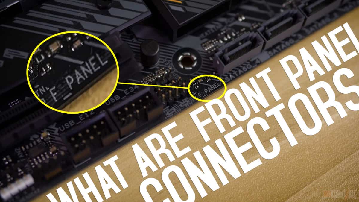
All motherboard connectors have labels assigned to them to make them easier to find. In the same vein, the front panel connector of the motherboard also has its designated label.
They are commonly labeled as FPanel, F_Panel, or FPheaders. Look for all these different names on your motherboard, and you will find the front panel connectors of your motherboard.
Typically speaking, start your search from the bottom edge of the motherboard. Most motherboards have their front panel connectors at that spot, so it is best to begin your search from the bottom.
Also, the front panel connectors are primarily around the edges, so focus your search around the edges while gradually making your way inwards.
Not going to lie; finding the front panel header this way is the hardest, and you are better off using the motherboard manual. Let me tell you why.
Locating the Front Panel Connectors by Using Motherboard User Manual
The motherboard’s user manual is the definitive guide for locating all the ports on a motherboard. It has a labeled diagram of your motherboard with its different ports. Those ports also include the front panel connectors of the motherboard.
If you don’t have access to a motherboard manual, don’t worry; you can easily download a soft copy of it by going to your motherboard’s manufacturer’s website.
Now that you have the motherboard user’s manual navigate to the contents section. Look for Motherboard Overview in the contents section. After finding, open the specific page of the motherboard that has information about front panel connectors.
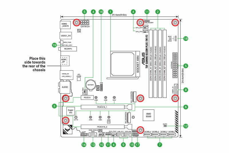
On that page of the manual, a complete diagram of your motherboard will be available with the front panel connectors clearly highlighted as FPanel, F_Panel, or FPheaders. After seeing this diagram, you will be instantly able to find the front panel connectors on your motherboard.
How to Tell What Each Pin in the Front Panel Connector Is Used For?
After you have found the front panel connectors of your motherboard, you should be staring at a barrel of different pins with no way of finding out what they do.
Well, don’t worry, I am here to tell you what each of them does by using two different ways.
The first way to understand the different pins of the front panel connectors is to read the physical labels beside them. That can be a rather tedious task because you will have to locate the label and then decipher it, which at times cannot be an easy task itself.
Therefore, I don’t recommend this method even in the slightest.
The second way to know what each pin does is to refer to the motherboard’s user manual. This is my preferred approach because the motherboard manual has information laid out more clearly and concisely.
So, grab yourself the motherboard user manual and open the front panel connector page, where all the information about them is listed.
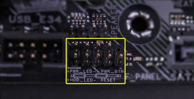
You will have a similar picture in your motherboard’s manual like the one below. The picture will have all the pins labeled according to their function.
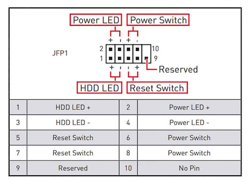
Of course, slight variation can occur, but generally, the arrangement of the front panel pins is like the picture you are seeing in this article.
The top row pins consist of a power LED, and a power switch, respectively, while the bottom row has hard drive activity LED, and a reset switch in that order.
A quick tip I can give you for making your life a little easier is remembering that the power switch and the reset switch come in the same third and fourth columns. Some PC cases will only require you to plug in these two cables, so knowing their location is very helpful.
Follow the diagram and remember the location of each of the pins because you will be connecting the corresponding front panel cables to their respective front panel header pins.
For example, the power LED will be connected to the PWR_LED pins of the front panel connector, while the power button cable will be connected to the PW_BTN pins of the front panel connectors. If you plug the cables into the wrong pins, they won’t work as intended.
What Cables Need to Be Connected to the Pins of the Front Panel Headers?
The cables you will be connecting to the front panel connector pins will be the ones that are coming from the PC case. Your PC case won’t necessarily have all the front panel cables; hence you will not need to populate every pin.
Typically, most PC cases come with at least three cables, that being the power switch, reset switch, and power LED indicator, so I hope you know where these three cables connect to.
With these cables, you will most likely see the HDD LED indicator thrown in, but that’s about it. The MSG, CL, and speaker cable don’t come with that many PC cases, so these three pins will be left vacant most of the time.
Does the Orientation of Cables Matter When Plugging Them In?
Many people believe that the orientation of front panel cables does not matter, but that is not the case. Some front panel cables and the pins have the + and – terminals.
When a cable is plugged in, ensure that you have plugged the – terminal of the cable in the – pin and the + terminal of the cable into the + pin.
If you don’t follow the alignment right, your PC case’s LEDs and buttons won’t function. The orientation especially matters for LED light, specific cables such as power LED, the hard disk LED, etc.
The only cables you can plugin without worrying about the orientation are the power switch and the reset switch. But don’t think that the orientation of every cable does not matter because of these two.
What Are the Advantages and Disadvantages of Front Panel Connectors?
Front panel connectors are very useful in your daily routine. Tell me how many times you use the power button to start your PC. Consider for a moment that your PC doesn’t have the front power button, and the only way to turn it on every time is to jump-start the motherboard.
This can be very inconvenient, and you will be fed up with it after a while. Therefore, having these small things like the Power button, reset button, power light indicators, and HDD indicators outside the case makes using the computer very convenient.
The only disadvantage of front panel connectors is that they are quite challenging to set up for novice PC users. Take up a lot of time that should otherwise be better off invested in other PC components.
Can the Front Panel Connector Be Used to Jump-Start the PC?
Front panel connectors come in very handy for jump-starting a PC when the power button is not working. The PW pin which connects the power button to the motherboard is located in the front panel header and we will be using this to jump-start the motherboard.
Grab yourself a screwdriver and touch the two Power SW pins simultaneously. That should power on your motherboard and your PC.
How Can the Front Panel Connector Be Used to Diagnose a Faulty Motherboard?
The motherboard’s ability to exhibit beep codes when under stress is very handy for diagnosing a motherboard. Checking for motherboard beep errors is a common practice to check a bad motherboard.
Front panel connectors have four speaker pins for the beep code error speaker. Some motherboards come with beep code speakers, and in that case, you will only need to plug the beep code speaker wire into the 4 speaker pins on the front panel connector.
Alternatively, one can also buy a separate beep code speaker and connect it to the corresponding speaker pins of the front panel connector to check the motherboard’s status and condition.
Related Guides
Check out some of our related motherboard buying guides.
- Best Ryzen 5 3600 Motherboards
- Best Ryzen 5 5600X Motherboards
- Best Ryzen 7 5800X Motherboards
- Best Ryzen 9 5900X Motherboards
- Best Gaming Motherboards
- Best B550 Motherboards
Check out some of the other related motherboard guides.
- How to Update Motherboard Drivers
- Do Motherboards Have Bluetooth?
- How to Install Motherboard
- How to Upgrade a Motherboard
- How to Reset Motherboard
- What are Motherboard Standoffs?
- What the Red Light on a Motherboard Means?
Conclusion
Front panel connectors are used for many different tasks. They are more than just facilitators for the PC case and have a much larger function.
One thing no one can deny is that they have made things so much easier for consumers, and without them, even turning the PC on would require a complex process.
The front panel connectors are not the easiest to connect and can take quite a bit of time to connect because of the small pins. However, some modern motherboard and PC cases come with a single connector solution for the front panel connector rather than a collection of different pins which makes the whole procedure very intuitive and easy.
This is, however, limited to high-end motherboards only and it is time that every motherboard should have this feature.
This wraps up our article on what are front panel connectors. Before I sign off, tell me how much time you spent connecting the front panel cables of your motherboard. Also, tell me which cable was the hardest to plug in.
The Author Who Worked On This Article
David Wiley
David is a profound researcher who loves writing about PC gaming and new technology. He had access to a computer ever since he was young and this passion for computers eventually drove him to major in computer science.