Is your motherboard not working correctly, or have you bought a new motherboard that needs to be checked? Either way, you will need to test your motherboard.
A motherboard is an intricate and delicate electronic component. As a result, it can be quite tricky to diagnose it if anything goes wrong.
However, don’t worry this article will provide you a simplified guide on how you can test your motherboard. This article will begin with the basics and progress to the more advanced technician stuff so whether you are a beginner with zero PC knowledge or a seasoned PC veteran, this article has information for everyone.
Sounds good? Well, then stick around because, as we progress you will have full confidence in how you can diagnose your own motherboard and save money in the process.
There is a lot of information to cover, so let’s get straight to that.
Tools You Will Need to Test Your PC Motherboard
Don’t worry; there aren’t any complex tools I want you to arrange. I am pretty sure you will already have access to these tools, and if not, you could always borrow them.
You can also splurge the money for these tools if you don’t have them since they will also be of great use even after this motherboard testing process is done.
Anyhow, the following are the tools you need to have to test your motherboard.
- Philips Head Screw
- A new CMOS battery cell
- CPU thermal paste
- Multimeter to check the voltages
- A properly working Power Supply (PSU) in your PC
Besides the multimeter, all the other tools are fairly straightforward, so I don’t think I need to tell you about them. The multimeter, however, is a semi-professional tool used for measuring voltages for PC components and other electronic gadgets.
This device has diverse applications and is helpful in many different scenarios, so you should keep one at home if you don’t have any.
Is a CPU Needed to Test the Motherboard?
Yes, a CPU is needed to test the motherboard properly. While you could skip the CPU and do dry testing, the process for that is very complex and frankly beyond what an average person can do.
For testing the motherboard without the CPU, refer to my in-depth guide on how to check motherboard without the CPU.
What Are the Symptoms of a Faulty Motherboard?
While testing can verify our doubts about the motherboard, it doesn’t hurt to know beforehand where the problem in the motherboard exists.
If, before starting the testing process, you already have a general idea of what is wrong with the motherboard, then it will be easier for you to test and verify it.
Therefore, take it for what it is and do this preliminary preparation work to make the testing process easier. I know it is not an easy task to find where the problem in your motherboard exists. Therefore, I have a thorough article on checking a bad motherboard, which will help you to a great extent.
What Do the Errors in the Motherboard Mean?
During motherboard testing, you will encounter two sorts of errors. As the name suggests, the first is the beep errors signified by consistent beeps when a motherboard is turned on.
The second sort of error fall in the category of malfunction, and they are signified by random restarts, crashes, blue screen, failure to boot, etc. These errors are typically displayed in the form of a code. For example, a particular error might have the code (ABCD-780001xxx). Whatever error code you get that can be google-searched for further evaluation.
In this section, we are more interested in why these errors occur. Therefore, next are some of the diagnostics you can run a motherboard through to figure that out.
POST
Power-on-self-test or POST is the self-checkup state of the computer when you first attempt to boot it. During POST, a computer checks all of its components to see if they are in working order and only then boots to the Windows.
If any error is present in POST, the computer won’t boot and will be stuck in a boot loop. The boot loop is a state in which a computer tries to boot again and again only to return to its starting position.
The POST could be one reason why your motherboard is not working as intended because until all the motherboard components are cleared, the POST won’t allow the motherboard to function.
Shorting
Shorting is the term used when the cable or the wire from the motherboard touches the bare metal surfaces of the case. This can result in an unwanted transfer of electricity that is unsafe and quite destructive for the motherboard.
A motherboard is a complex electronic circuit, so any such shorting can result in a motherboard malfunction.
Simply slide open the case and check all the loose cables to identify shorting. See if any loose cable is making contact with any metal component. Sometimes, some stray metal components can also make contact with a neatly tucked-in wire, so be on the lookout for that.
Overheating
Heat is the kryptonite of every electrical component, and the motherboard does not escape that wrath. Any accumulation of heat inside the motherboard can greatly affect the delicate electronic components of the motherboard.
The heat could result from many different factors, but the one that tips the scales is dust accumulation. The gradual buildup of dust can choke the computer for air, resulting in overheating.
The dust is especially prevalent around the computer fans, so check those out. To clean the dust from your PC, it is best to use a can of compressed air.
Flashing LEDs
Modern motherboards have troubleshot LEDs. These LEDs light up if there is an issue with the motherboard. Typically, a motherboard has four LED lights for CPU, GPU, BIOS, and Memory.
Depending on the error, the responsible LED will light up to signify the source of the error. Motherboard LED lights are a great and easy way to diagnose any issue with the motherboard.
These LED lights are usually located to the right of the CPU socket and above the 24-pin ATX power cable of the motherboard. However, some motherboards can have them in other places as well.
If you are receiving this error and want to know more about it, check my article on what the red light on the motherboard means.
Beep Codes
Your motherboard has a speaker that gives out different beeps if it detects any failure in the motherboard. These beeps are in the form of codes and the number of times the beep sounds corresponds to a specific error.
For example, there can be a 3 beep sound, 5 beep sound, or even 7 beep sound. To find out more about beep codes, check out my article on how to tell if a motherboard is bad. Long story short, the following is what each beep code means.
- 1 Beep- faulty or misaligned memory
- 2 Beeps- bad motherboard
- 5 Beeps- faulty CPU
- 9 Beeps- issue present in the BIOS or ROM
This is just the gist of it and there can be many other beep codes as well. For the full summary of what each beep code means refer to the PCMag.com beep code article.
However, what if your PC does not give any beep codes. Well, then it is most likely that the beep code speaker is missing in your motherboard.
Don’t worry though installing this speaker is quite easy and it is quite cheap too. After buying it you have to install in the specific front panel header pins labeled as speaker + and -.
CMOS Battery
The CMOS is a coin battery that powers on the motherboard. Think of it as a car battery. A car cannot start without the battery and so cannot the motherboard with the CMOS battery.
This is because this battery is responsible for starting the BIOS of the motherboard. Being a cell-type battery, it has its shelf life.
If the battery’s shelf life exceeds the time you have it in the motherboard, then it is basically weak and of no use. If that happens, your motherboard won’t be able to access its BIOS, so it won’t function as a result.
BIOS
The BIOS is an integral part of a motherboard, and it controls all the aspects of the motherboard on the software side. Being software controlled, the BIOS is not prone to corruption.
When that happens, a motherboard can no longer function. Therefore, keeping your BIOS up to date with the latest updates from the manufacturer is the way to go. check my article on how to update motherboard BIOS.
Updating the BIOS adds new and improved features to the motherboard and irons out any defects that may be building up in the motherboard BIOS.
The Methods for Testing Your Motherboard
Okay, since now we have cleared all the preliminary checkmarks, let’s proceed to the actual process of testing a motherboard. I will be telling of three methods that can help you check a motherboard in different capacities.
All these motherboards will have a step-by-step guide to make them easy to understand and follow. The methods are in no order, so try them all to get the best results, and with that said, let’s jump to the first method.
Method 1: Check if the Motherboard Boots to the BIOS
The BIOS is the operating system that conveys all the motherboard information to the users. It allows the motherboard to communicate to different parts of the PC, resulting in a coherent PC in its operation.
Suppose a motherboard can boot to the BIOS. In that case, it shows that a motherboard is in its working. Having access to the BIOS allows users to extract information on all the aspects of a motherboard and test it to its fullest.
This method works both for currently installed motherboards already in your PC and the fresh motherboard you need to install. However, the technique for both differs slightly in the few steps, but then the rest of the process is the same.
For a Motherboard Inside the PC
- Open the side panel of the case
- Now that you have access to the motherboard, remove all the parts that are not a part of this process.
- Firstly, remove the graphics card by unscrewing the thumbscrew holding the graphic card to the case.
- Next, pull the latch of the slot to which the graphics card is attached. Now gently pull the GPU until you free it from the PCIe slot. Finally, rest the GPU on the side
- Now remove all the unwanted cables that we don’t need, including SATA cables, fan cables, RGB cables, front panel cables, etc.
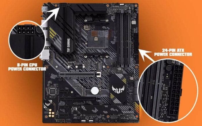
- The only cables that need to be plugged in are the 8-pin CPU power cable and 24-pin ATX power cable.
- After removing unwanted components and cables, you will have a motherboard with a CPU and RAM connected, and that is what we need.
For a New Motherboard
- Take out the motherboard from its box and set it on top of it or alternatively, you can use a wooden table and rest the motherboard on it.
- Open the CPU socket by unlatching the pin holding the CPU socket cover.
- Place your CPU in the socket, ensuring that the arrow on the CPU aligns with the arrow on the CPU socket.
- Pop open the RAM slots by pushing out the two handles. Align the RAM hole with the corresponding hole of the RAM slot and push it in.
- You should hear a snap indicating that RAM is installed successfully.
- Now, take your PSU and set it next to the motherboard.
- Install the 24-pin ATX cable of the motherboard. The slot for this cable is usually at the right of the CPU socket.
- Next, install the 8-pin CPU power cable. The slot for this cable is located close to the CPU socket
- Plugin the power cable of the power supply into the wall socket.
- Connect the display cable from the back of the motherboard to a monitor. You can use any display cable, for example, HDMI, VGA, DisplayPort, or VGA.
Steps That Apply to Both
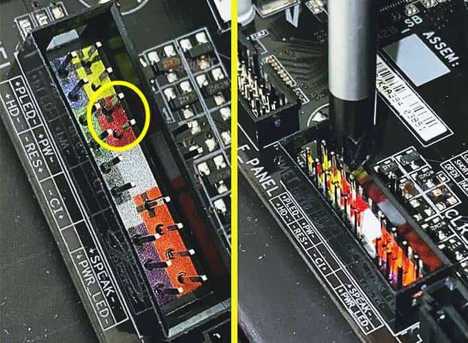
- Let’s try jumpstarting the motherboard. For this, you will need just a screwdriver and the location of the front panel header on the motherboard. To find the front panel header, you can check your motherboard’s user manual.
- On the front panel header, there will be 2 pins that correspond to the PW+ and PW-
- Place your screwdriver in between the two motherboard pins. The screwdriver should touch both of the pins simultaneously.
- This should start your motherboard right up.
- Now that the motherboard is on, observe for any errors or beeps. If no errors and beeps are found, the motherboard should run normally.
- Turn off the PC by disabling the power supply with the on/off switch.
If, after following the method, your motherboard boots into the BIOS just fine without any errors, it is in good condition. However, if your motherboard exhibited any beeps or errors after starting the PC, then I am afraid it is not in the best of conditions.
However, to further find out what is wrong with the motherboard, we have to conduct a few other tests to help diagnose the beeps and the errors.
Method 2: Check With System Fans
If the first method has not netted any results, you can test the motherboard by using the system fan approach.
In this method, we basically connect the motherboard to the case fans of the PC and then turn the PC on. Our main objective is to see whether the fans spin or not.
The method for this process is as follows:
For a Motherboard Inside the PC Case
- Slide open the side panel of the PC case
- Remove the GPU, RAM, and other components attached to the motherboard
- Only keep the CPU installed
For a Motherboard Outside the PC Case
- Place the motherboard on top of an anti-static object. Ideally, use the cardboard box that the motherboard comes in or a wooden desk.
- Open the CPU socket by pulling out the pin that holds in the plastic cover.
- Install the CPU into the motherboard
Steps That Are Same for Both Situations
- Use either the case fans or the CPU fans and connect them to their respective motherboard header.
- You will need to have a CPU installed in the motherboard for the CPU fan method to work.
- The header for the CPU fan is located near the CPU socket.
- You will need to refer to the motherboard’s user manual for the case fan header or find the 4-pin port labeled as SYS fan.
- Connect the 24-pin ATX power cable of the motherboard and the 8-pin CPU power cable into their respective header.
- Jumpstart the PC
- If the fans start spinning after starting the PC, that indicates that the motherboard is in working condition.
This is a simple method to verify if the motherboard works or not. It doesn’t dive into the intricacies of the motherboard and only checks the functionality of the motherboard as a whole.
Method 3: Test the Motherboard by Using a Multimeter
If you have tried everything to no avail, don’t worry because, with this final method, you will be able to fully test your motherboard and decide if it needs replacing.
A multimeter is an electronic device that allows users to measure the voltage of electrical leads and circuits.
To test the motherboard we will be measuring the voltage of the 24-pin motherboard power connector. Ideally, what we are looking for is that each pin of the motherboard should have a specific voltage value.
Before I begin with the method, let me tell you this is more of an advanced method, and therefore, if you fail to understand it on the first attempt, don’t worry and give it a second or a third try. If you still are unable to understand it, then ask me in the comment section where you are stuck for clarification.
With that being said, let’s dive straight into the method.
How to Check Voltage Using Multimeter
To check the voltage using a multimeter, do the following:
- Make sure that the ATX power connector is plugged into the 24-pin ATX header on the motherboard.
- Switch on the PC and turn it on, even if it is not running.
- Grab your multimeter and set it to the lowest setting i.e. 200 or 0.1. Make sure the multimeter points to these numbers
- A multimeter has red and black prongs. Attach the black prong to ground level. The easiest way to do this is to insert the black prong into any ground connector of the motherboard and make sure it is plugged into that connector throughout this process.
- Now starts the tricky part. Navigate to the 24-pin ATX power connector of the motherboard.
- The 24-pin ATX connectors will have different color cables attached to it. We are going to test the yellow, blue, orange, and red cables.
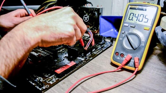
- To test any cable insert the red prong of the multimeter into the backside of the pin of the ATX power connector where the cable is attached to it. Basically, follow the cable to its hole and put the red prong into it.
- The orange cable should read +3.3V, red cable +5V, yellow cable +12V, and blue cable -12V.
- Test the orange, red, yellow, and blue cables, respectively, and see if you get the reported voltage.
- After you are done with all of them, remove the red prong of the multimeter first and then the black prong.
It is a lengthy process and it will take time, so you have to be patient with it. After you are done with this process, see if the values you have obtained by testing the orange, red, yellow, and blue ATX pins of your motherboard correspond to their actual voltage value.
A slight variation in the margin of (+)(-)0.1-0.2 is acceptable. For example, if you are getting 11.98V reading instead of 12V then it is fine. Similarly, if you get 5.1V instead of 5V then that is fine as well.
If your motherboard is showing different values altogether or is not registering any voltage value then it is highly likely that your motherboard is fixable beyond repair. In that case, you will need to visit a hardware professional.
However, the quote for fixing the motherboard if it can be saved will be astronomical, so it is better to replace the motherboard and the power supply.
Related Guides
Check out some of our related motherboard buying guides.
- Motherboard for Ryzen 5 3600
- Motherboard for Ryzen 5 5600X
- Motherboard for Ryzen 7 5800X
- Motherboard for Ryzen 9 5900X
- Motherboard for Gaming
- B550 Motherboards
Check out some of the other related motherboard guides.
- How to Update Motherboard Drivers
- Do Motherboards Have Bluetooth?
- How to Install Motherboard
- How to Upgrade a Motherboard
- How to Reset Motherboard
- How to Check What Motherboard Do I Have
- Can You Upgrade CPU Without Changing the Motherboard
Final Thoughts
With all the methods now complete, it is time to wrap up the article. Every method mentioned in this article works to a varying level of degree.
Also, each method will be best suited to different scenarios. Therefore, I recommend giving all the methods a shot.
However, my personal favorite is testing the motherboard with a multimeter because it provides the most definitive results.
That is not to say other methods don’t work, and you should try them too. You never know which method works wonders in such a delicate piece of electronic gadget.
In the comment section, I want you to tell me which method worked for you. Also, if you have difficulty in any of the steps, do tell me down below. I hope you liked the article and the information mentioned in it is helpful.
The Author Who Worked On This Article
David Wiley
David is a profound researcher who loves writing about PC gaming and new technology. He had access to a computer ever since he was young and this passion for computers eventually drove him to major in computer science.