Plugging in each individual front panel cable into its respective pin on the motherboard can be painstakingly difficult, but what if I told you there is an easier way for connecting the front panel connectors?
In this article, I will tell you how you can connect the front panel connectors to the motherboard simply and easily—no more frustration due to wrong pins and mismatching terminals.
But how will this be done? Well glad you asked. The following is what will be included in this article.
- Negative and Positive terminal identification
- The complete layout of the front panel connector pins
- Step-by-Step guide on how to connect each front panel connector
Sounds exciting, doesn’t it? So, without further ado, let’s begin.
Where Is the Front Panel Connector Header Located on the Motherboard?
To connect the front panel cables, the first thing we have to do is identify where the motherboard port for the front panel header is located.
You can locate the motherboard’s front panel connectors in two ways.
- By physically searching for it on the motherboard until you locate it
- By reading the motherboard’s user manual
If I am being honest, going with the first method is a game of luck. You will either find the front panel connector on the motherboard within seconds or even after 10 minutes; you will be without any meaningful result.
Therefore, I believe you should use the motherboard’s user manual to see where the front panel connector is located. I know some folks may not have access to the user manual of their motherboard. I mean can’t fault them for not keeping a piece of document in 2022.
Either way, it is very easy to download the motherboard manual through the manufacturer’s website. Head over to your motherboard manufacturer’s website and search for your motherboard model.
Once you have found your motherboard model, open its support page and head to the resources section. From here, download the user manual.
Now, open your motherboard’s user manual and navigate to the page where information about front panel connectors is given.
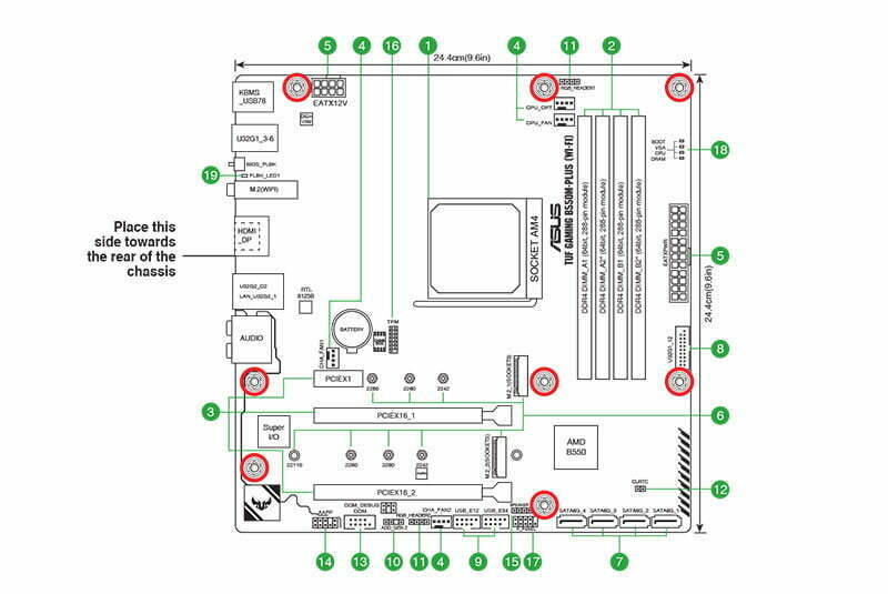
On this page will be a labeled diagram of the motherboard. The diagram will clearly highlight where the front panel connectors are on the motherboard. Use this information to locate the front panel connector on your motherboard.
Prepare the Front Panel Cables
After you have found out where the front panel header of your motherboard is, the next thing to do is prepare the cables coming out of the PC case for an easy connection.
Preparing the cables involves arranging them in order and then routing them through the motherboard’s backside. We need to route the cables through the proper channels. If we directly plug in the cables without routing them, it would mess up the cable management.
To route the front panel cables through the back to the following.
- Separate the front panel cables from the rest of the bundle
- Untie these cables and route them to the back of the PC case through the cutout near them.
- On the backside, run these cables through the proper channels and bring them to the bottom of the motherboard
- Pull these cables up from the cutout closest to the motherboard’s front panel port.
- Inspect all the cables. If any cable is loose, then tuck it in properly. You can also use zip ties to hold the cable to the case firmly in place.
The Method to Connect the Front Panel Cables to the Motherboard
Now comes the scary part. Connecting all the different front panel cables can seem like a very daunting task, especially where you have to connect the tiny 2-pin cable. But I guarantee you that you won’t encounter any issues if you follow my guide right.
I will split this guide into two sections. The first section will focus on the front panel connectors coming from the PC case. The second section will focus on the other cables coming from the PC case that need to be connected to the motherboard.
1. Connecting the Front Panel Connectors to the Motherboard
The general layout of the front panel header of the motherboard will look something like the picture down below.
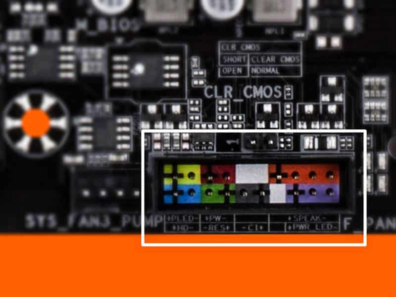
Starting from the top row, the first 2 pins will represent the Power LED, followed by the power button pins.
The Power led pins will also have the + and – terminals labeled. If they are not labeled, it is safe to assume that the left pin is the + pin and the right pin is the – pin.
Moving onto the bottom row, the first two pins will be for HDD LED, and the next 2 will represent the reset switch pins. You can also assume that the left pin is the + pin while the right pin is the – pin in this row.
Almost 90% of the PC cases will only require you to connect these four cables to the motherboard. So, knowing about them is all that is needed.
Since now I have familiarized you with where the cables are going to connect, I reckon now you will be able to follow the steps in the guide pretty easily. So, let’s get to them, and we will focus on connecting these cables one by one.
Power LED cable
- Grab both of the power LED cables.
- One will have a + sign, and the other will have a – negative sign.
- Plugin the cable with the + sign first into the left pin of the two-pin arrangement.
- Now, plug the – cable into the right pin of the two-pin arrangement.
HDD LED Cable
- Grab the HDD led cable and plug it directly below the Power led cable
- Make sure the side of the cable with the text is facing upwards when plugging it into the 2 pins.
Power Button
- The two pins next to the power LED are the power button pins
- Plugin the power cable of the PC case in these two pins, ensuring that the side with the text is facing upwards
Reset Switch
- The reset switch cable plugs in directly below the power button cable
- However, you will need to plug in the – terminal first to connect this cable.
- You can do that by inverting or flipping the cable.
- Insert this cable into the 2 pins with the text side facing downwards.
- Now that these four cables are plugged in, we are almost 70% done connecting the case’s front panel connectors. The other cables are pretty easier to connect than these four cables.
2. Connecting the Front USB and Audio Ports to the Motherboard
Along with the power button, reset switch, and LED indicators, a PC case also has audio and USB ports. There are at least two types of USB ports, i.e., USB 2.0 ports and USB 3.0.
Both the USB 2.0 and 3.0 ports have separate connectors on the motherboard. The following is how you can connect the audio and the USB ports to their designator ports on the motherboard.
USB 3.0
The USB 3.0 is a very distinct cable with a blue-colored header. You can easily identify it by looking at the picture below because it differs from all the other cables coming from the PC case.
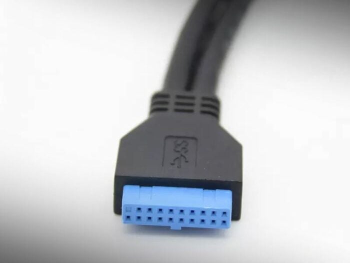
The connector for this cable is also very distinct. You can either find it by searching on the motherboard for a port with the F_USB30 label or refer to the motherboard’s user manual. Generally speaking, the USB 3.0 header is located at the bottom of the motherboard.
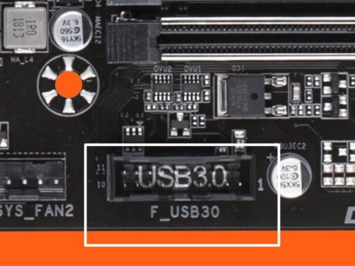
Use the reference picture to find the USB 3.0 port. It will be in the same general spot as the front panel connectors, so finding it won’t be difficult.
Once you have found the USB 3.0 header, simply plug the USB 3.0 cable into it. To plug the aforementioned cable correctly, align the pins of the cable to the pins of the connector.
USB 2.0
USB 2.0 header is a little harder to identify than USB 3.0 because the header has the same general layout as the HD audio header.
Nonetheless, it will be in the same row as the USB 3.0 header. Also, USB will be spelled inside its socket, so be on the lookout for that. Besides that, it will also have the typical F_USB label around the header.
To give you a pointer, the following is what the USB 2.0 header looks like.
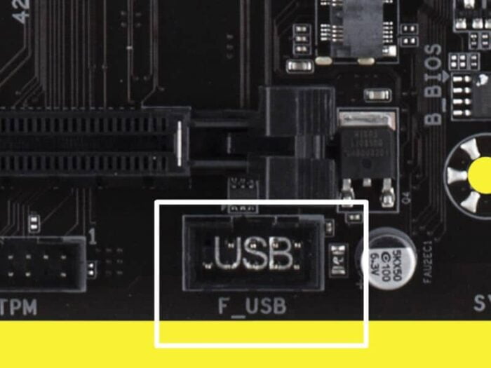
A USB 2.0 has 9 pins. The rightmost pin in the bottom row is missing, which is the identification for a USB 2.0 header.
When plugging the USB 2.0 cable into the USB 2.0 header, keep the missing pin in mind and align the cable accordingly. If your alignment and orientation are right, the cable should slide right in without any force.
HD Audio
The HD audio header has the same 9-pin configuration as the USB 2.0. The only difference is that the 9 pins on this port are arranged differently.
The HD Audio connector lacks the fourth pin of the first row, which is how you can easily identify this connector.
Anyhow, the following is what an HD audio connector on the motherboard looks like.
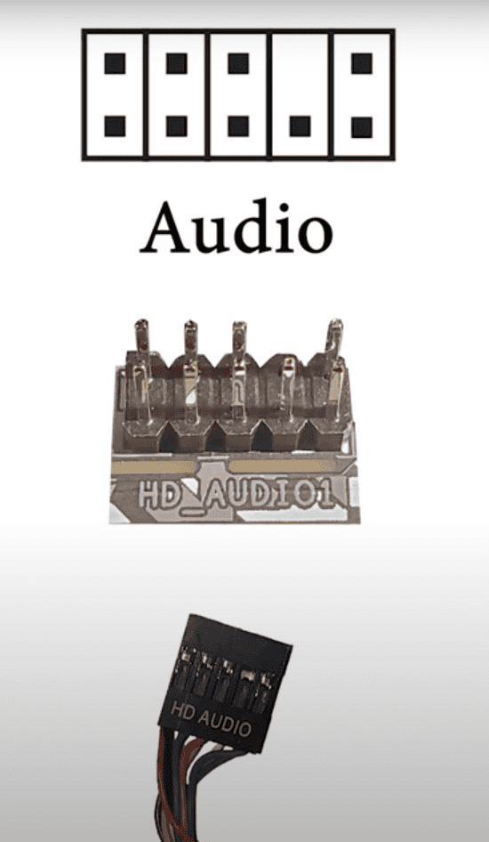
To insert the HD audio cable into its corresponding connector on the motherboard, you have to align the cable properly. Make sure that the cable aligns with the missing pin according to its specification. Once it does, push the cable into the port.
Related Guides
Check out some of our related motherboard buying guides.
- Motherboards for Ryzen 5 3600—Top Picks
- Motherboards for Ryzen 5 5600X—Top Picks
- Motherboards for Ryzen 7 5800X—Top Picks
- Motherboards for Ryzen 9 5900X—Top Picks
- Motherboards for Gaming—Top Picks
- B550 Motherboards—Top Picks
Check out some of the other related motherboard guides.
- How to Test a Motherboard
- What Are Front Panel Connectors?
- What are Motherboard Standoffs?
- What the Red Light on a Motherboard Means?
- What Are PCIe Slots? (And Their Uses Explained)
- How to Tell if Motherboard Is Dead?
Final Thoughts
Time to finally close the side panel of your case because these were all the front panel connectors that you needed to connect to the motherboard.
Among the PC case cables, the most tedious to connect are the front panel cables. In contrast, connecting the USB and the HD Audio cable is quite straightforward.
However, don’t take them lightly because if you plug them wrong you can easily bend the pins hence causing permanent damage to the motherboard and the cable.
Use the pictures I have provided above for a smooth and easy installation and feel free to ask in the comment section if you are having any trouble. Also, do let me know if this article made it easy for you to connect the front panel connectors to the motherboard.
The Author Who Worked On This Article
David Wiley
David is a profound researcher who loves writing about PC gaming and new technology. He had access to a computer ever since he was young and this passion for computers eventually drove him to major in computer science.